The road to nirvana |
|
My journey into Photography, Horology, and Audiophilia |

AK-200 Preamplifier
Using the Western Electric 407A and variants
After I built the Foreplay, my friend handed to me a pair of 5670 tubes and said try them instead of the 12AU7. I made a prototype and changed the part values for the 5670 but it never made any sound. That was the end of the story for the 5670.
Fast forward, somebody sold cheap Western Electric 407A and I said, Wow! I can own a Western Electric tube and I bought two pairs :-) I then revisited the common grounded cathode-> cathode follower configuration, made a prototype using the 407A and liked how it sounds. It stayed like that for a while and replaced the Foreplay in my system.
Later on, I found out that the following 6.3V filament tubes- 2C51, WE396A, and the 5670 have similar operating characteristics as the 407A. As opportunities appropriately came, I ended up with Raytheon 2C51, Western Electric 407A, 407B, and 396A. I also got a pair of RCA 407A, and the previous 5670 turned out to be a dud, that's why it did sound at all. A friend has about 300 pieces of 5670 branded "El Gato" and I'd like to have a pair or two.
I got side tracked and made a 12B4 preamp in the process. Which I really liked due to the simplicity- one tube per channel and a few parts. After completing that project, I decided to go back to the two stage 407A and tried to make it simpler- ditch the cathode follower. I entered the 407A tube parameters into TubeCAD to check the output impedance which turned out to be around 3K. What the heck, just try it.
Took out the tube graph and tried to check the loadlines again.
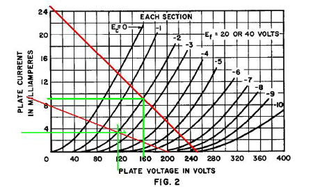
Previously I was operating it at much lower current and for this iteration, I like to run it hotter at around 8-9mA.
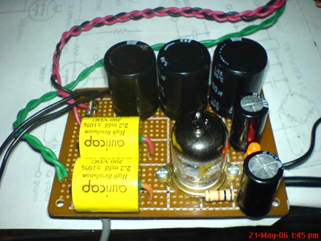
I was lazy to make a decent PCB so I used a prototyping board for this project. Also installed a switch so I can change from 40V to 6.3V filaments depending on the tube I want to roll.
I used LED biasing that I became a fan of after reading the experiments of SY at diyAudio. I asked lots of questions in this thread. As a future modification, I plan to use the diyAudio CCS board as plate load instead of a plate resistor. Nothing extra ordinary on parts- cheap LED, carbon resistor, Auricap for output capacitor, which happens to be cheap here (dealer is my friend, he he) and from the same source, an ALPS Blue. Electrolytic capacitors are generic, maybe Taiwan made.
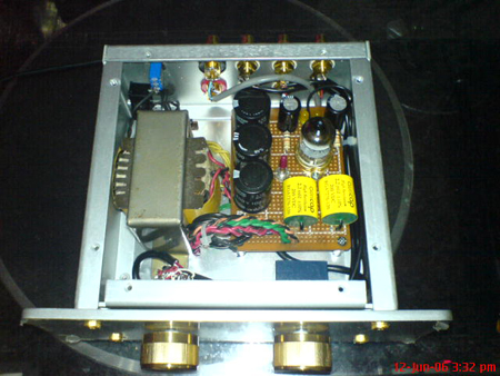
Here is how it looks now, in what I think is a nice aluminum chassis with hairline finish.
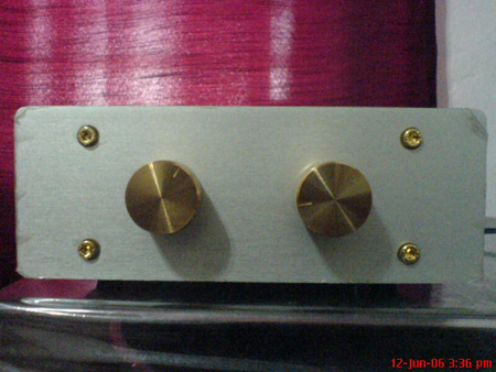
Here's the front. Thought the gold-like finish of the knobs matches well with the brass screws. Darn, the plastic protector is still on the faceplate. :-)
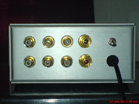
I haven't installed a decent EIC connector yet. Has three inputs and one output.
Here's a peek on the inside. A little bit cramped and I've been monitoring the dissipation which is around 45 degrees centigrade. The aluminum will get a bit hot as it becomes a big heatsink.