The road to nirvana |
|
My journey into Photography, Horology, and Audiophilia |

PCB milling using the Snapmaker A250
August 20, 2020
In the distant past, I've always used Ferric Chloride etching process with my PCB for my finalized projects but that currently doesn't appeal to me anymore.
Most of the time, I end up using perforated boards or prototyping boards to finalize my project, the recent one being my enclosure sensors.
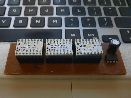
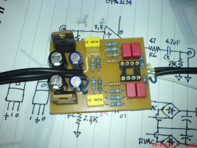
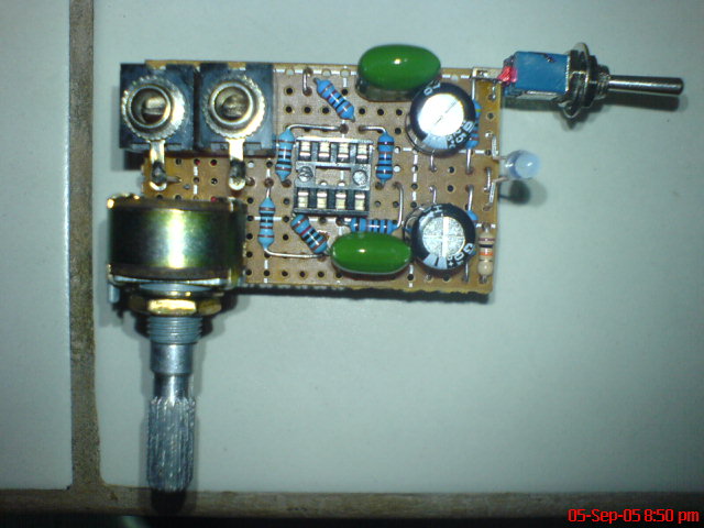
Back in 2005, I made about three dozen CMoy headphone amplifers as a community service for members of a local headphile group.
Thus, when the Snapmaker 2 hit Kickstarter one of the things I wanted to do is use CNC for milling PCB. I've had the A250 for a while but hasn't really looked into the matter, until now.
Software requirements
Ideally, having a schematic design tool that can produce the PCB layout is ideal and thankfully, there are a few of them available. The next challenge is converting the PCB layout to a set of machine instructions the industry calls G-code for milling and again, we are thankful that the software developers got it covered.
- Schematic/PCB design tool - my favorite is DipTrace, it's only available for Windows though. The MacOS version is not native, it's a repacked Windows version running via Wine. I've used KiCAD, Eagle, and a few other PCB layout tools in previous life but DipTrace connects with me better.
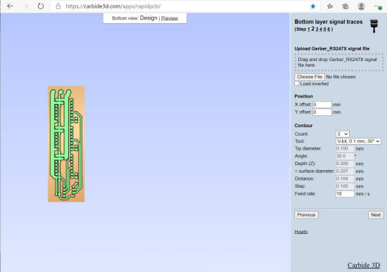
- Carbide Copper is Carbide3D's latest version of their web-based CAM software for milling PCB with a CNC machine. The legacy version Rapid PCB is still available and in some situations is the solution for dealing with Gerber files that is offset for reasons unknown to me.
Once the Gerber and Excellon formatted files have been exported from DipTrace, here are the steps to produce the G-codes for milling.
Using Gerber and Excellon formatted files with Carbide Copper (and the legacy Rapid PCB)
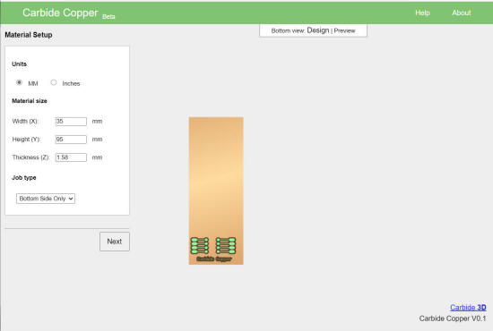
- Material Setup - set the size of your PCB and whether you're doing a bottom side or top side job.
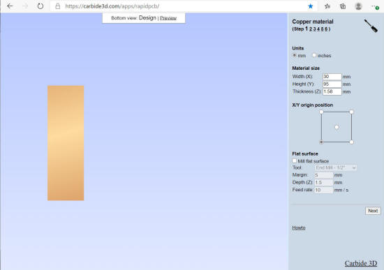
-
Copper Layer - this is where the Gerber file needs to be loaded and tool for milling chosen. Be aware that a) there is no way to specify a position X, Y offset unlike in Rapid PCB and b) the bits are different, i.e., there's no 0.1 mm 30° V-bit available like that in Rapid PCB. Set the Isolation Passes and verify the result by zooming in on the PCB.
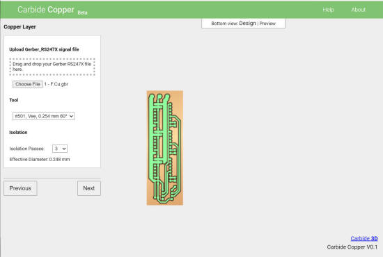
-
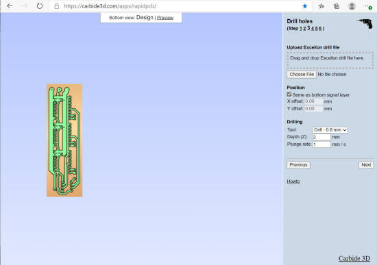
Drill Holes - load the Excellon formatted drill file and make sure they're aligned to the copper. In the Drilling section, you can specify the end-mill for drilling the holes. If you need to drill holes larger than 0.9 mm, you have to do it elsewhere.
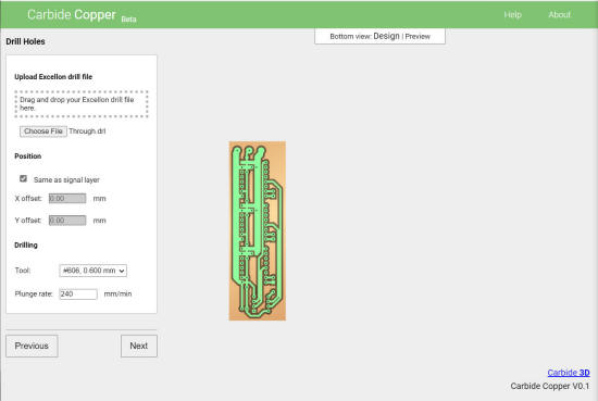
-
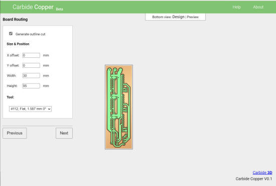
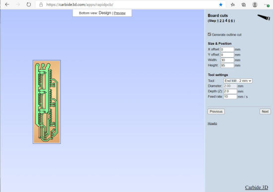
Board Routing - this is where you can specify the outline cut for the PCB, using a flat-end milling bit. Specify the boundary by setting the offset, width and height suitable for your needs. Take note that Rapid PCB has more options for the tool.
-
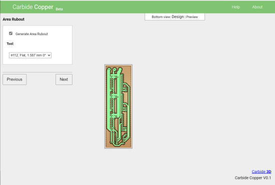
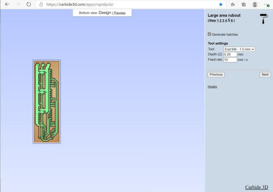
Area Rubout - you can also clear the copper that's not needed and just leave traces and holes using the specified end mill.
-
G-code Output - finally, generate the G-code for loading to Snapmaker Luban.
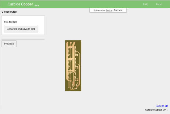
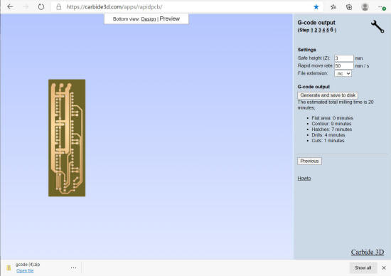
With Carbide Copper, a single NC file will be created that will contain all contour, drill, outline, and hatches passes. Snapmaker won't ba able to do a tool change!
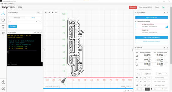
Rapid PCB on the other hand will produce a ZIP file containing files for each operation - contour, drill, hatches, and cut. You can load it into Snapmaker Luban in that order.
The contour pass.
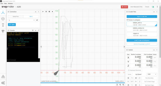
The drill pass.
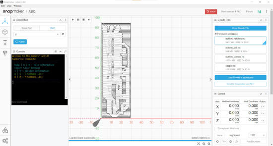
The hatch pass.
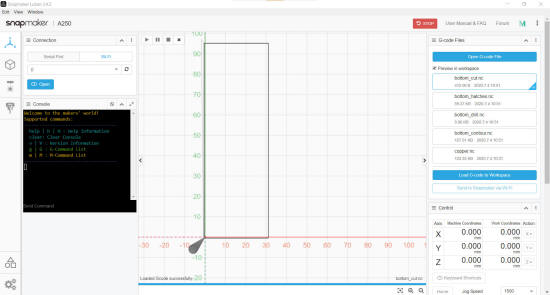
The cut pass.
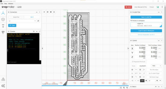
Running the contour and drill pass on my A250
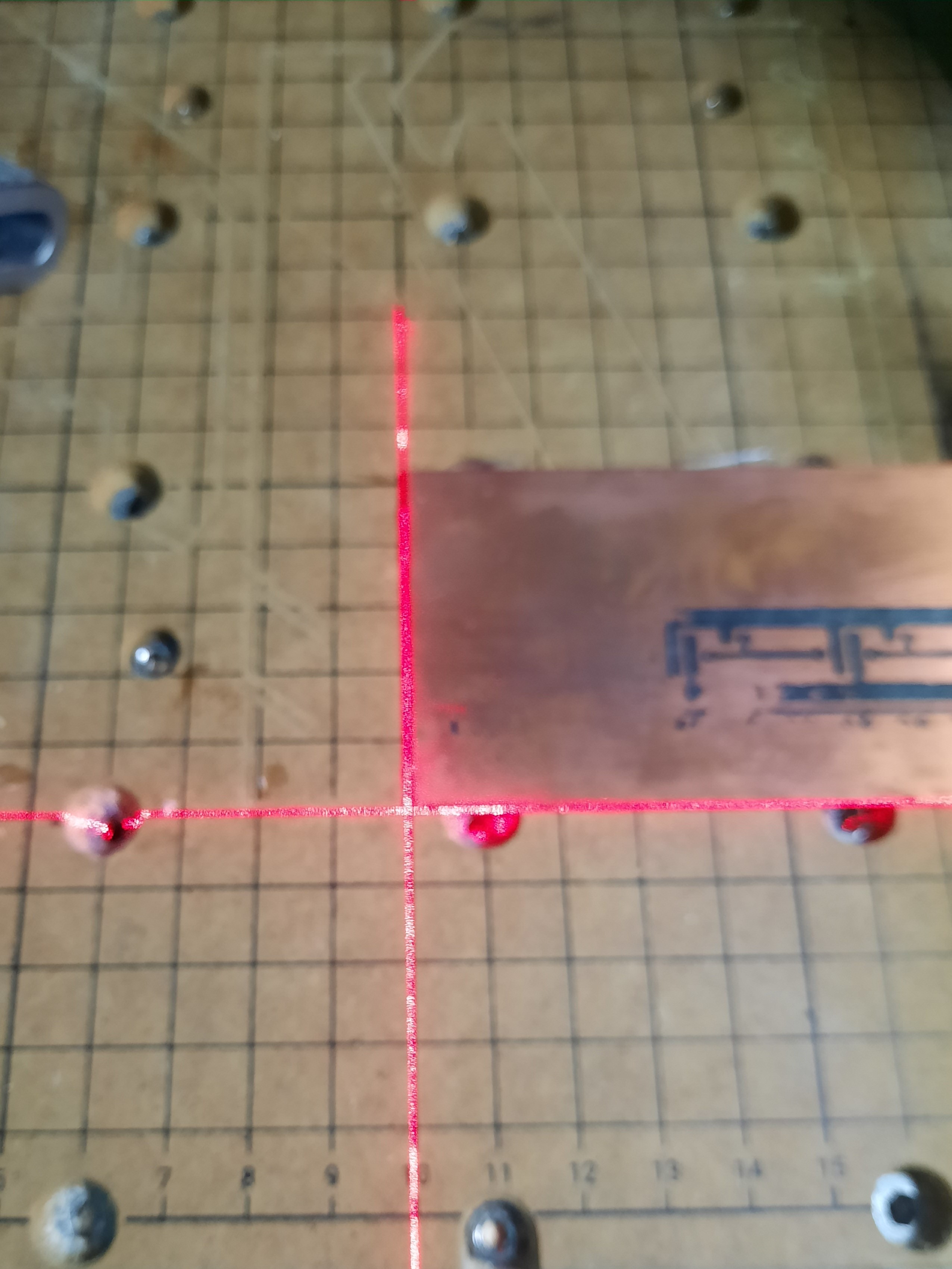
I'm using the lower left corner as the origin and my DIY laser guide makes setting the X and Y origin a breeze.
Next, I loaded my Boboaldo 0.1 mm 30° V-bit and set the Z origin. I ran a boundary in Snapmaker Luban to confirm the outline and started the job.
After a few minutes with 3 passes, the drill pass followed and here's the result.
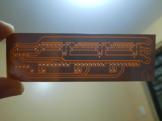
I'm pleased with the results.