The road to nirvana |
|
My journey into Photography, Horology, and Audiophilia |

Cetus 3D MK3 Extension Board and Heated Bed installation
April 22, 2019
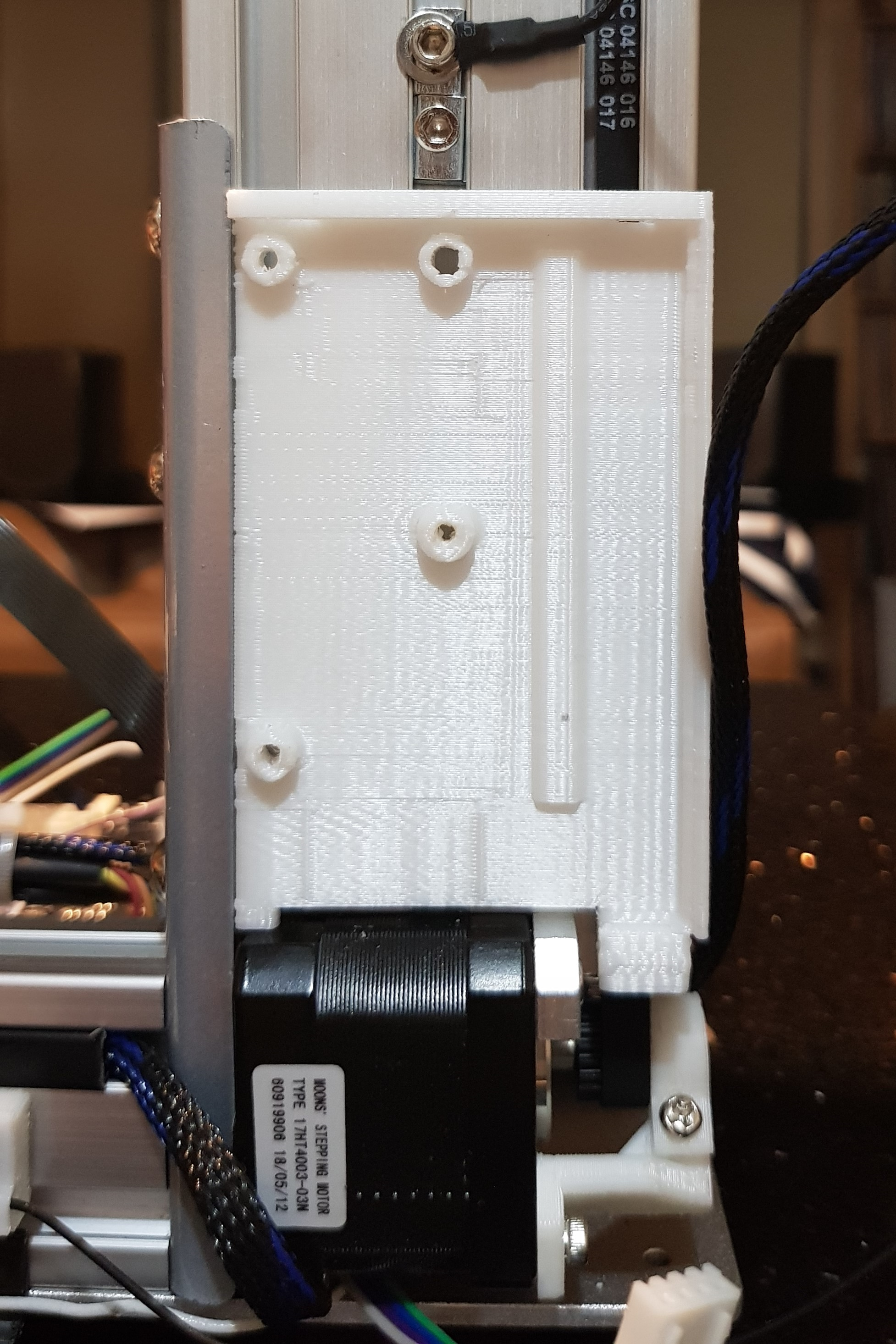
Cetus 3D MK3 printers have a small PCB under the cable guide (white, 3D printed part) mounted at the lower part of the Z pillar. This junction board splits the signal coming from the "Pyz" connector to the appropriate "Py" and "Pz" connectors. The objective of this upgrade is to replace this dumb junction board with a more functional (electronically, that is) Extension Board.
The Extension Board provides the same functionality as the junction board, plus high power (220W) 24V DC supply distribution, leveling probe support, as well as heated bed support.
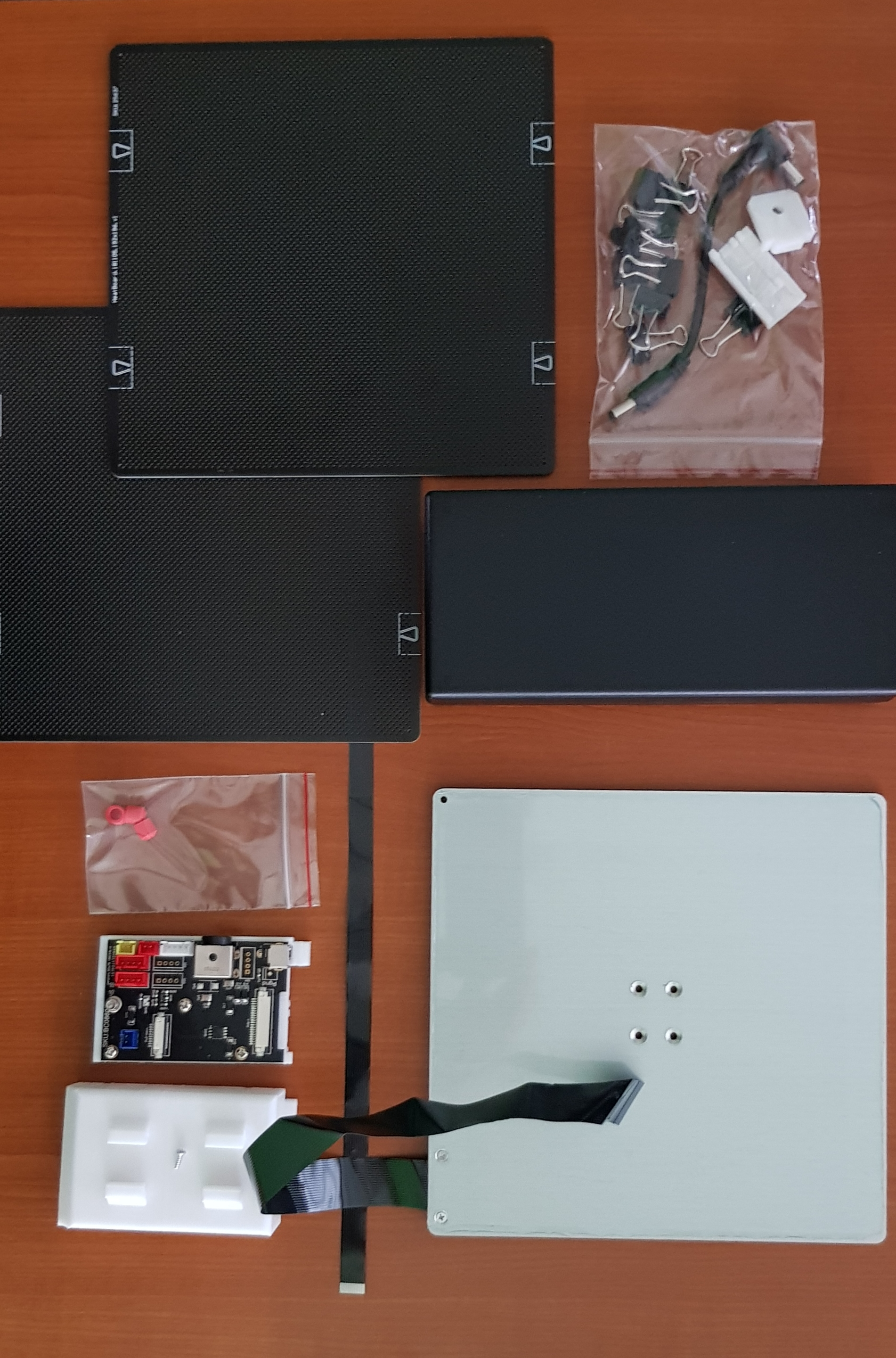
I ordered the parts from Tiertime that includes the 220W power brick, heated bed, extension board, and a few silicone tips.
Installation of the Extension Board
Installation of the extension board is pretty straightforward, remember that in its most basic form, it replaces the junction board. Therefore, the Pyz, Py, and Pz connectors simply plugs into the extension board.
- Unscrew the junction board PCB and cable guide at the back of the Z pillar, above the Z stepper motor.
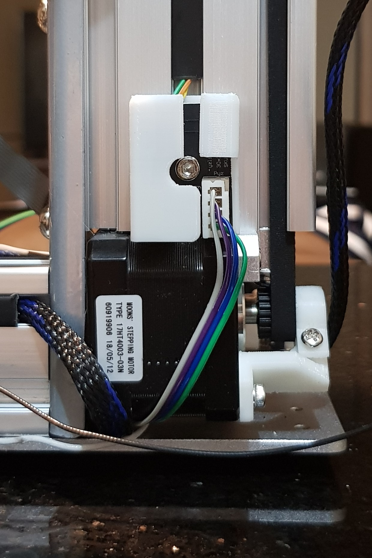
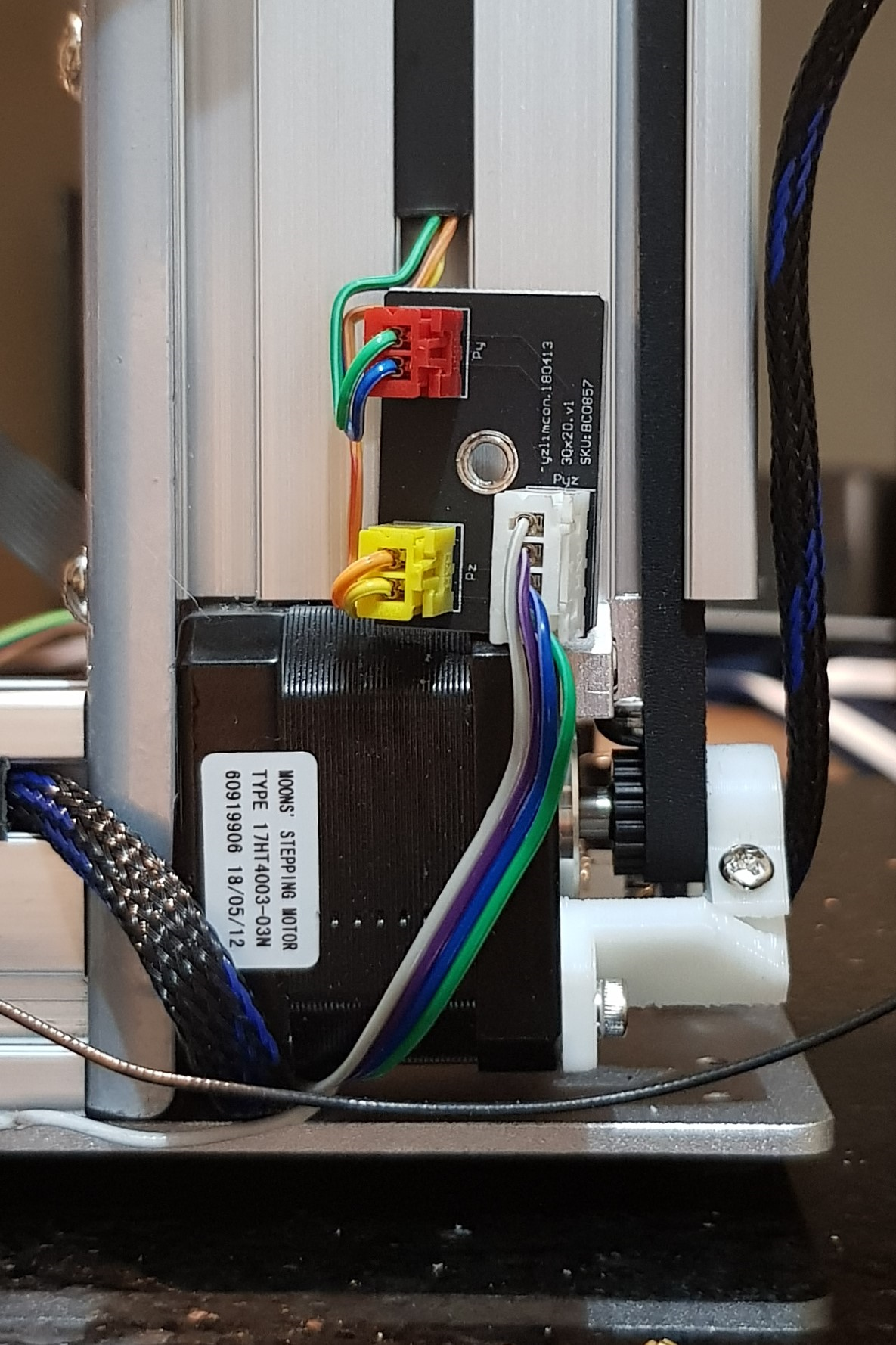
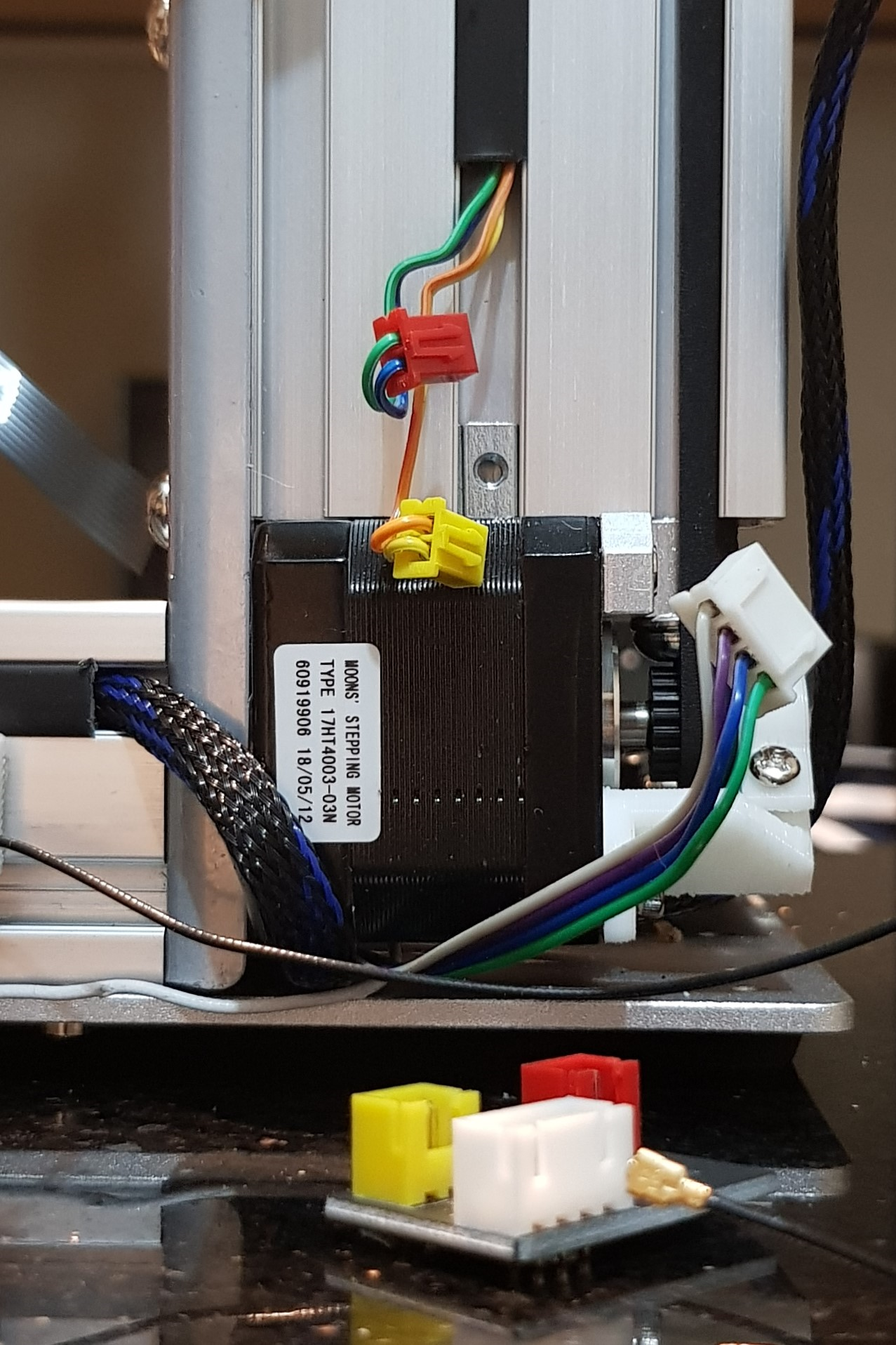
- Remove the Pyz (white), Pz (yellow), and Py (red) connectors from the junction board.
- Attach the supplied extension board base (3D printed part) to the back of the Z pillar using the supplied bolt and T-nut.
- Install the Extension Board into the extension board base using the supplied screws.
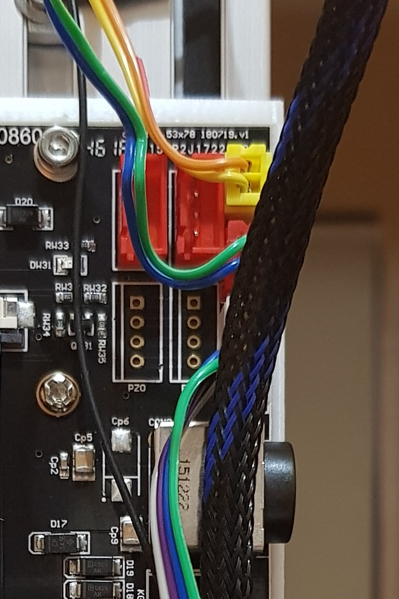
- Insert the Yellow and Red connectors into the extension board "Pz" and "Py" connectors, respectively.
- Insert the White connector into the extension board "Pyz" connector.
- Connect the power supply extension cable from the Extension Board to the main board power supply (the right angle connector).
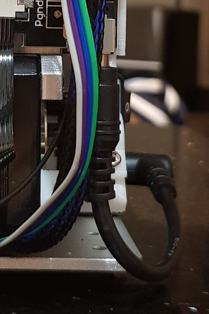
- Connect the 220W power brick connector (4-pins) to the Extension Board power input, CON2.
- Power on the MK3 and perform initialization and verify that all end stops are working.
Note: If you're going to use your own power supply, Tiertime includes an adaptor (yellow) where you can solder wires from your 24V DC power supply and then plug it into CON2.
Installation of the heated bed
- Remove the stock build plate.
- Remove the CPU cover.
- Insert and secure one end of the 10-connector ribbon cable (FFC) to the mother board "Pw2" (connectors facing down).
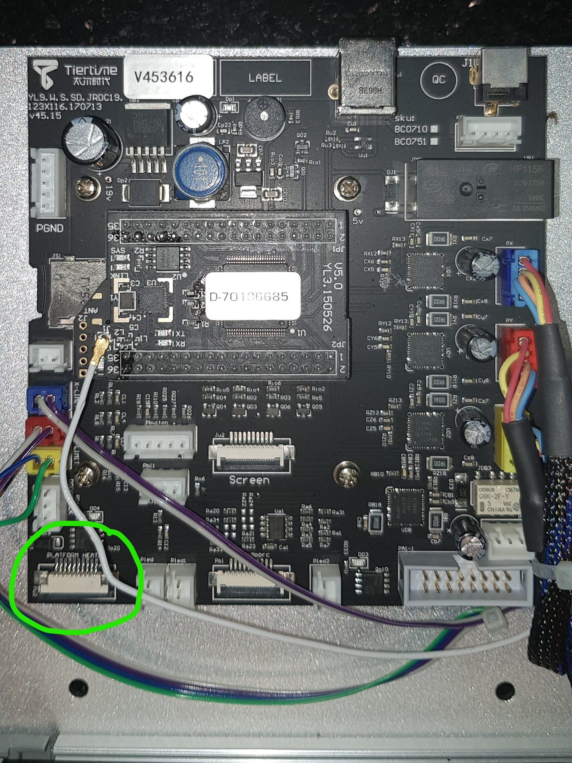
- Route the 10-connector ribbon cable from the mother board into the Z-axis gap going to the Extension Board.
- Insert and secure the other end of the (FFC) cable to the Extension Board "Pw2-main" again connectors facing down.
- Screw the Heated Build Plate into the linear rail and route the ribbon cable to the Z-axis gap.
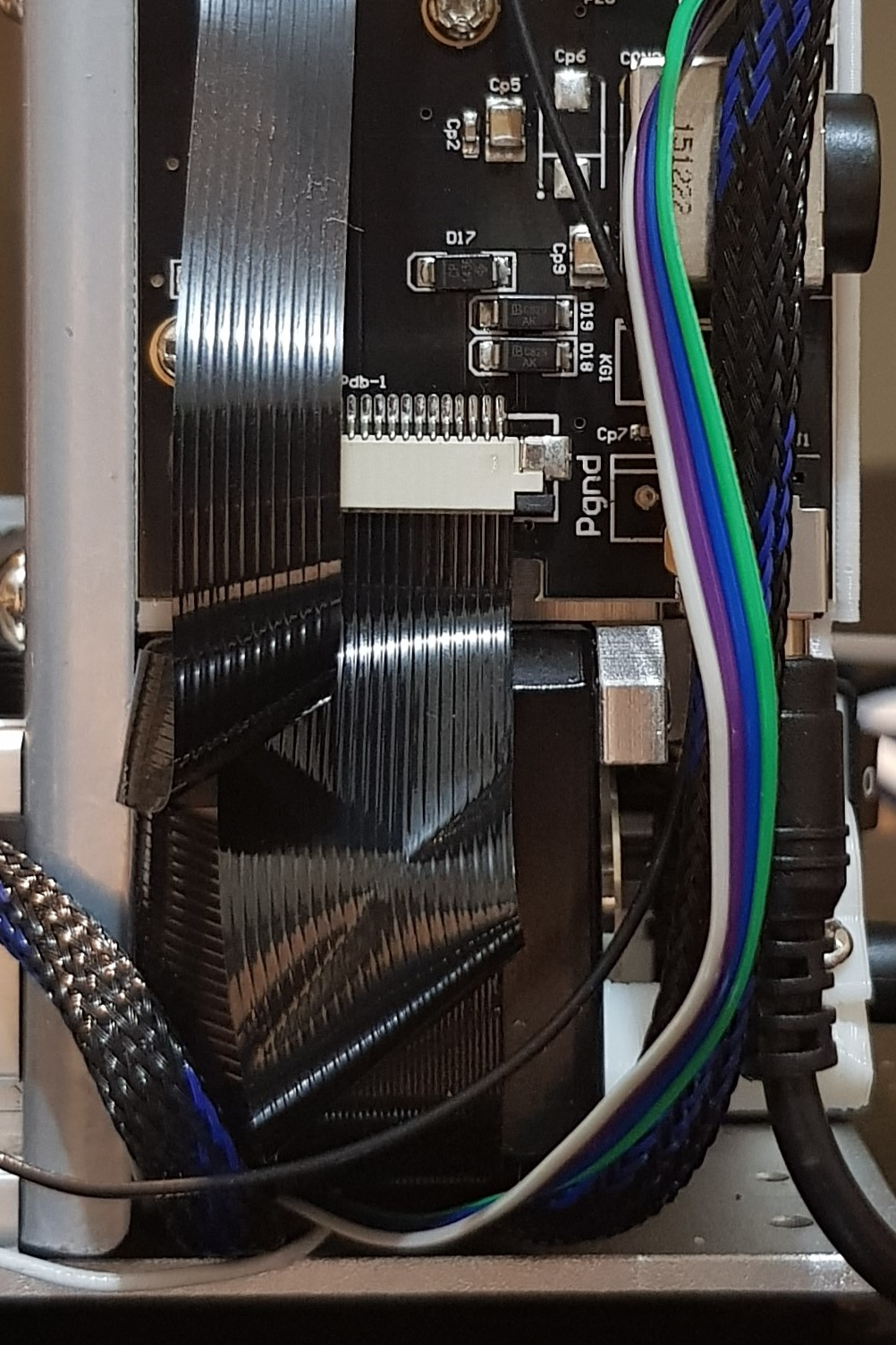
- Insert the Heated Bed 20-connector ribbon cable (FFC) end into the Extension Board "Pdb-1"(connectors facing up).
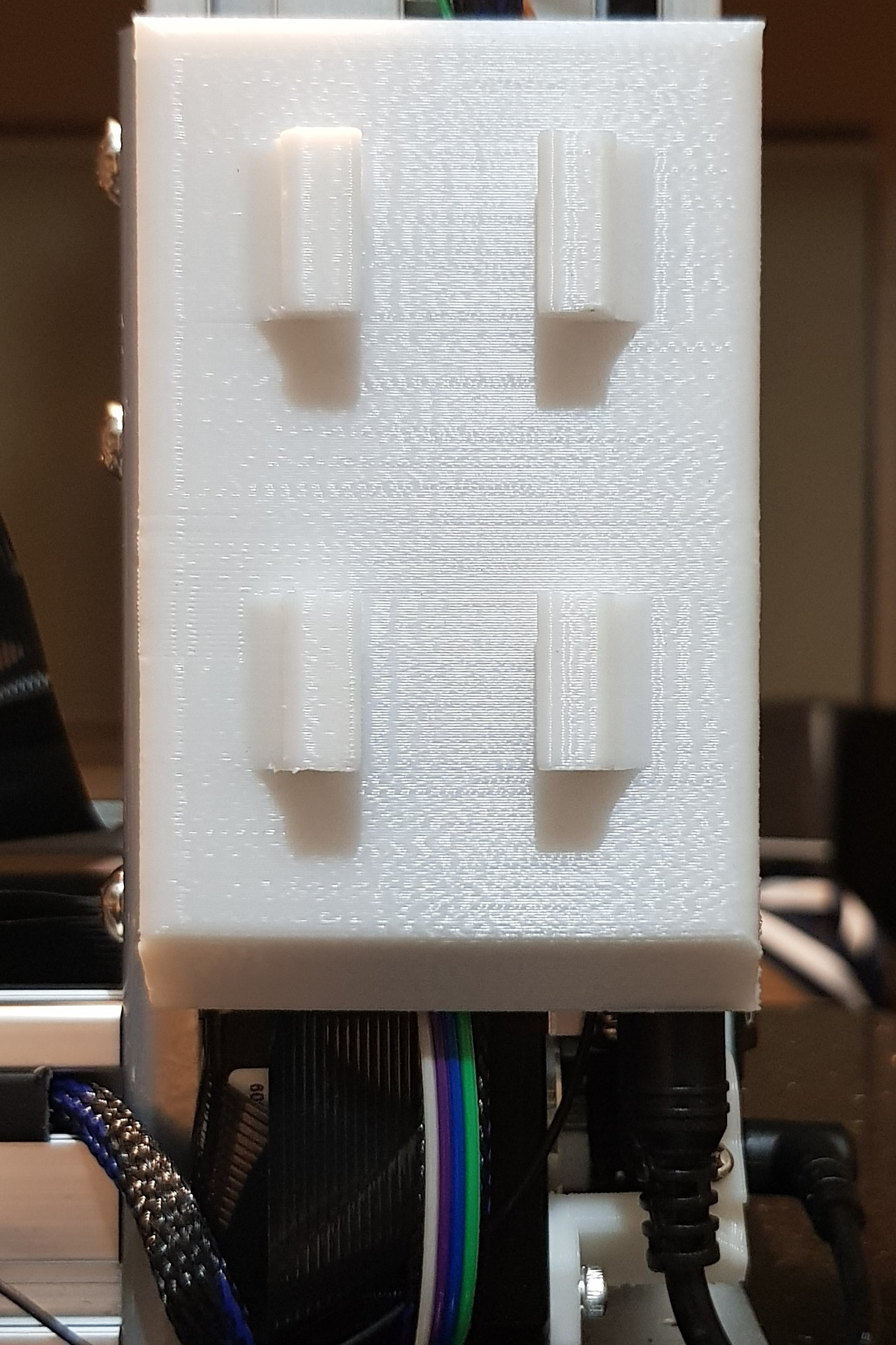
- Align the extension board cover and secure with the provided screw.
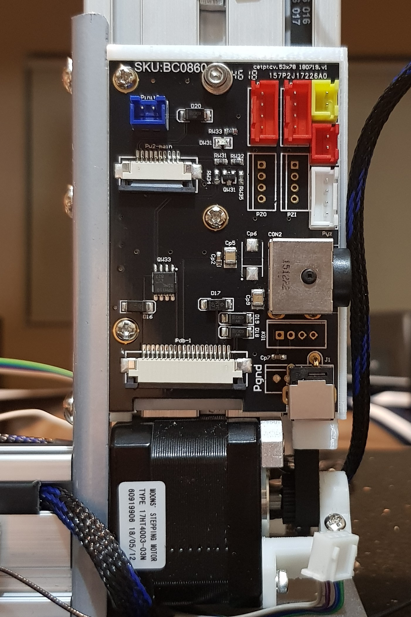
The Extension Board
Here are some of my notes about the extension board.
SKU: BC0860
- Pz (yellow, 2 pins) - connects to Z axis endstop
- Py (red, 2 pins) - connects to Y axis endstop
- Pinit2 (blue, 2 pins) - connects to calibration probe
- Pw2-main (white, 10-pin ribbon) - connects to main board Pw2
- Pdb-1 (white, 20-pin ribbon) - connects to the heated bed
- CON2 - connects to the 220W power brick
- J1 - connects power to the main board
- PYI (red, 4 pins) -
- PYO (red, 4 pins) -
- PZI (no connector) -
- PZO (no connector) -
- KG1 (no connector) -